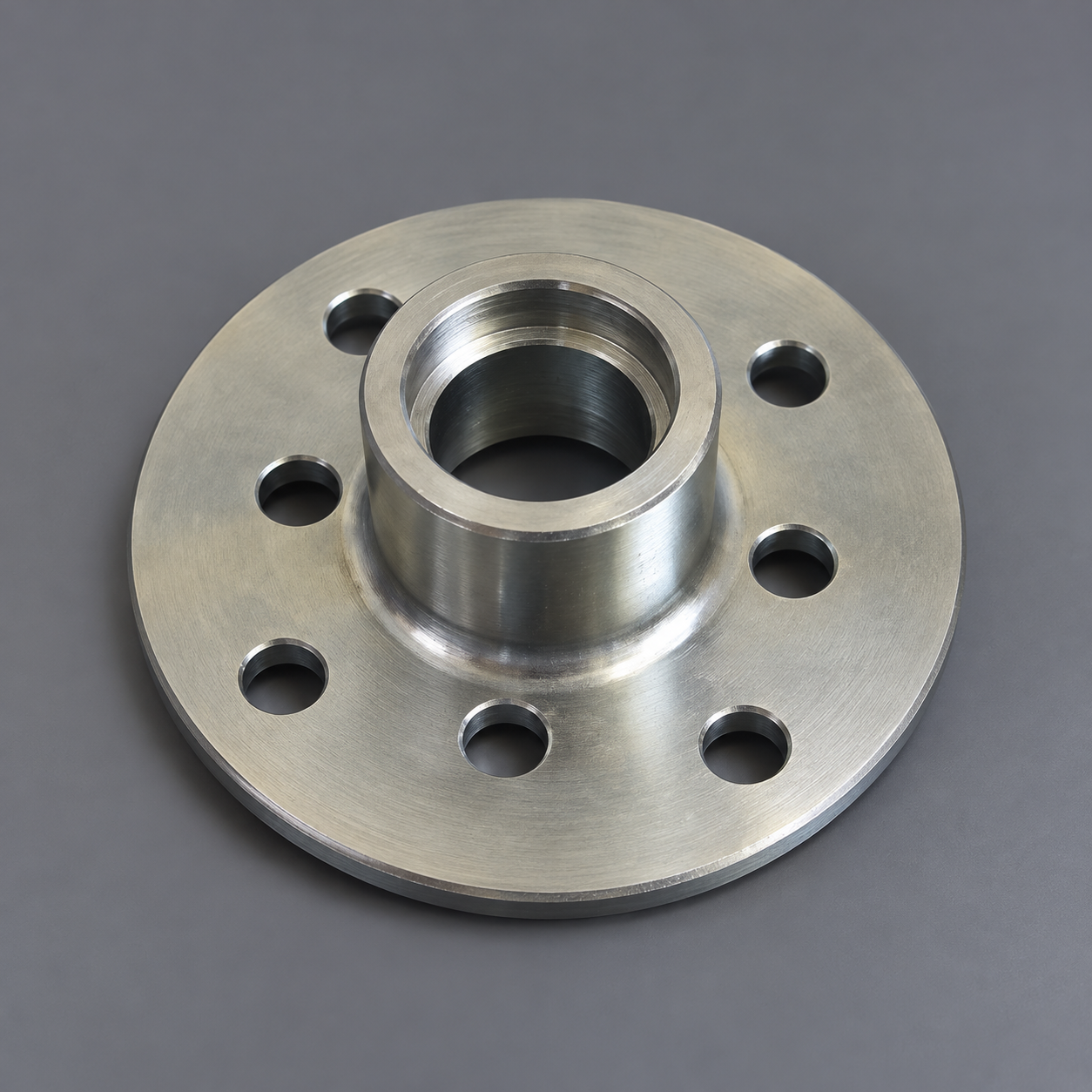

R10 Twin Bearing Block

From concept to production in 25 days High-quality, cost-efficient rapid tooling solution.

25 Days

Total Lead Time

±0.02 mm

Precision Tolerance

100K+ Shots

Mold Life

0 PPM

Quality Target

Project Overview

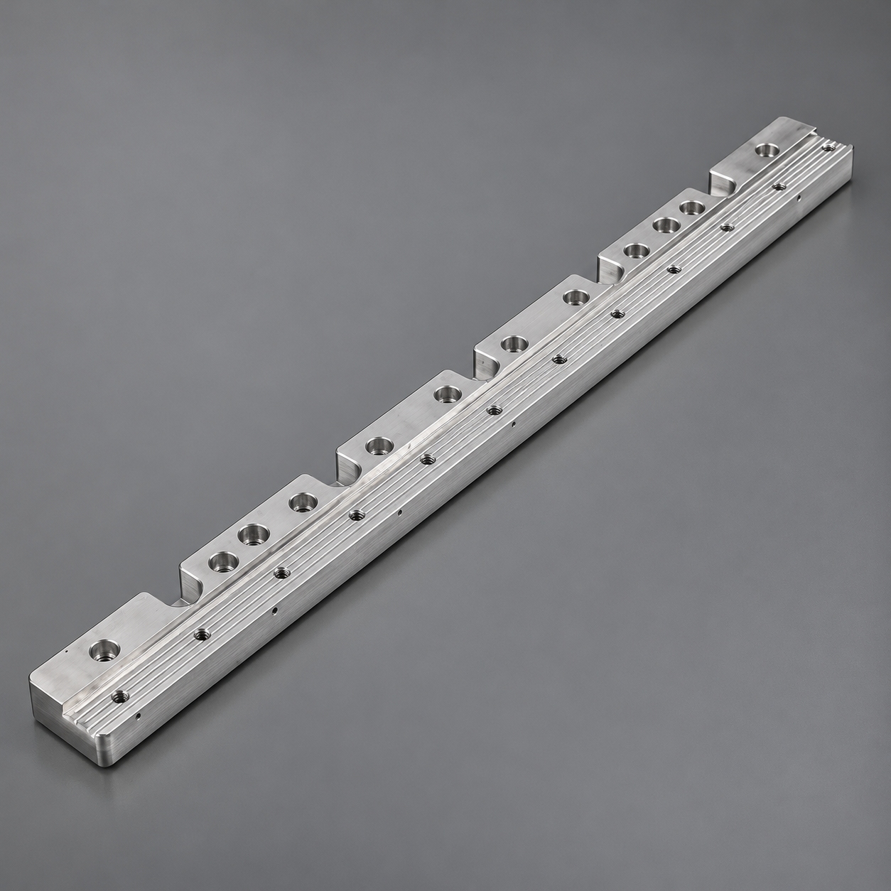
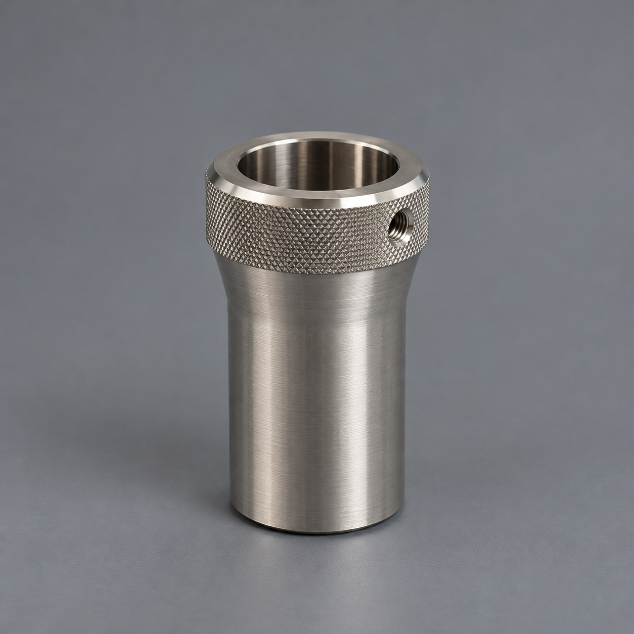
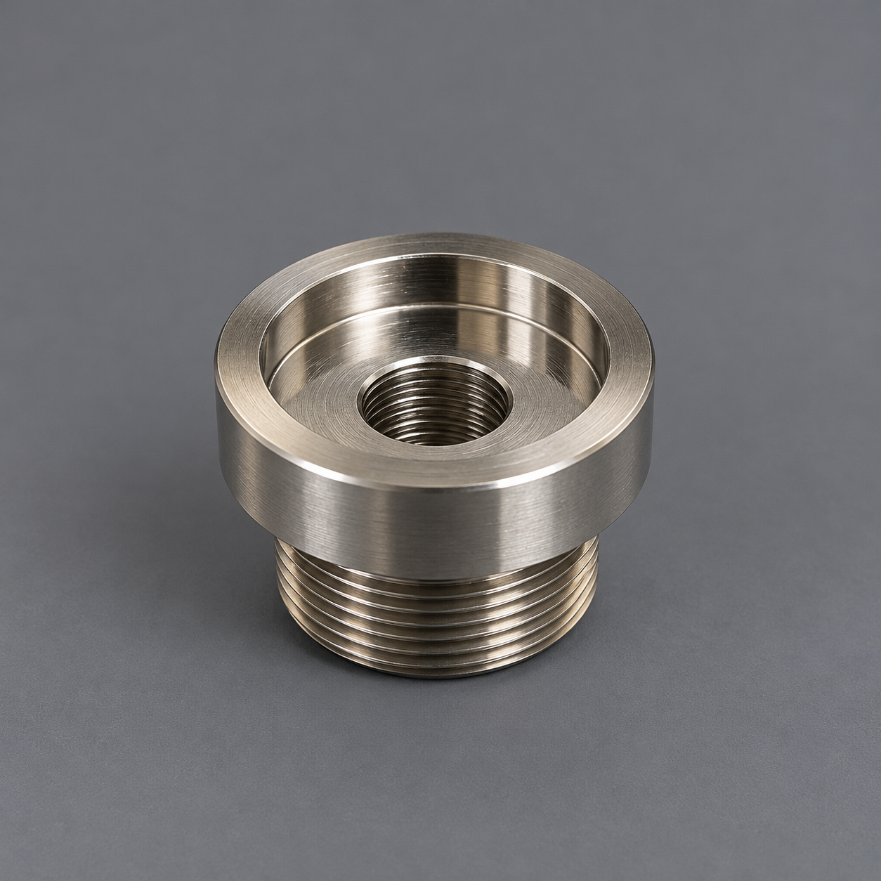
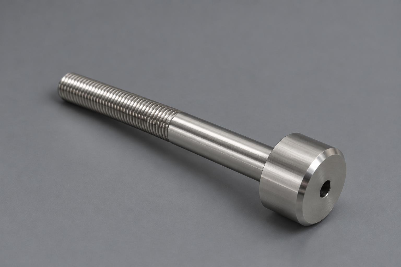
Manufacture of a precision R10 Twin Bearing Block for a robotic outdoor equipment platform. The component combines a Ø120 mm mounting flange, central stepped bearing housing and two precision Ø34.93 J6 bearing-seat regions. The part is manufactured from 42CrMo alloy steel and requires post-machining zinc plating, hydrogen-embrittlement relief baking and chromate passivation.
The component functions as a structural bearing support: it provides a rigid mounting interface while maintaining the concentricity and alignment needed for the rotating shaft/bearing assembly. For an autonomous outdoor machine, stable bearing positioning is important for smooth rotation, repeatable assembly and durability under vibration and field operation.

Item

Specification / Manufacturing Focus

Part Name

R10 Twin Bearing Block / Deck Bearing Support

Application

Bearing support and alignment component for a robotic outdoor equipment platform

Material

42CrMo alloy steel

Key Size

Ø120 mm flange; 33 ±0.1 mm overall height

Critical Bearing Bore

Ø34.93 J6 (+0.009 / -0.007 mm), two bearing-seat regions

GD&T / General Tolerance

Flatness 0.1 mm; geometric controls to datums A/B; ISO 2768-mK for unspecified tolerances

Surface Treatment

Zinc plating + hydrogen embrittlement relief baking + hexavalent chromate passivation; 12 h salt spray


Previous slide
Next slide

The Challenge

1. Precision bearing fits: the Ø34.93 J6 bores have a tight +0.009 / -0.007 mm tolerance. The two bearing-seat regions must be machined consistently so bearings can be assembled correctly without excessive looseness or interference.
2. Coaxiality and datum control: the drawing applies geometric controls relative to datums A and B. The central bore, bearing seats and mounting features must remain correctly aligned to avoid shaft binding or uneven bearing loading.
3. Flange flatness and hole location: the Ø120 mm flange has a 0.1 mm flatness requirement, while the four Ø10.3 mm and four Ø11 mm mounting holes have positional controls. Distortion or hole-location error could affect installation on the deck assembly.
4. Surface treatment after precision machining: zinc plating can change functional dimensions. Because the base material is high-strength 42CrMo, the drawing also requires baking for hydrogen-embrittlement relief. Critical fits therefore need process allowance and final verification after plating.
5. Cosmetic and functional quality: all surfaces must be flat and clean, with no burrs, sharp edges or scratches. The finished component must combine precision-machined bearing features with a uniform corrosion-protective finish.
Previous slide
Next slide

Our Solution

Use a controlled CNC turning + machining-center process. Machine the main rotational features from a common setup wherever practical to preserve concentricity between the central bore, bearing seats, flange face and outer locating features.
Establish datum A from the functional flange face and use the central cylindrical feature as the secondary reference corresponding to datum B. Finish-machine the critical Ø34.93 J6 bearing seats only after the primary geometry is stable.
Apply semi-finish and finish passes to the precision bores, using calibrated bore gauges / internal micrometers and CMM verification. Record actual dimensions of both bearing-seat regions rather than checking only one location.
Machine the mounting-hole patterns from the same datum system and verify their true position relative to A/B. Check flange flatness on a CMM or surface plate with an indicator.
Control plating thickness on critical fits by defining masking or machining allowance with the plating supplier. After zinc plating, carry out the specified hydrogen-relief baking and chromate passivation, followed by final dimensional and visual inspection.
Deburr all holes and edges, apply the unspecified C1 chamfers, protect machined surfaces during handling, and conduct a final inspection covering bore size, flatness, hole position, coating condition and surface defects.

Project Results

A robust bearing-support component with controlled bearing fits, aligned functional datums and repeatable mounting geometry. The manufacturing plan minimizes the risk of bearing misalignment, shaft binding and flange distortion while maintaining corrosion protection for outdoor service.
The completed part provides a reliable interface between the rotating bearing/shaft system and the equipment deck, supporting consistent assembly and long-term operation in a robotic outdoor-maintenance application. The documented dimensional checks and post-plating inspection also provide traceability for repeat production.

Project Photos

Customer Feedback

“

The tooling quality exceeded our expectations. The parts met all requirements and the lead time was impressive. We highly recommend their rapid tooling service.

— Project Manager, Automotive Lighting Company

Why Choose Us

10+ Years

Industry Experience

1000+

Successful Projects

Advanced Equipment

Precision Manufacturing

Strict Quality Control

ISO 9001 Certified

Global Service

Local Support

Have a Cast + CNC Part to Quote?

Send us your 2D drawing or 3D model. We can review the geometry, material, quantity and tolerance requirements and suggest a practical manufacturing route.

Drag & Drop Files, Choose Files to Upload
=