

Precision Threaded Adapter with Locating Flange
From concept to production in 25 days High-quality, cost-efficient rapid tooling solution.
25 Days
Total Lead Time
±0.02 mm
Precision Tolerance
100K+ Shots
Mold Life
0 PPM
Quality Target
Project Overview
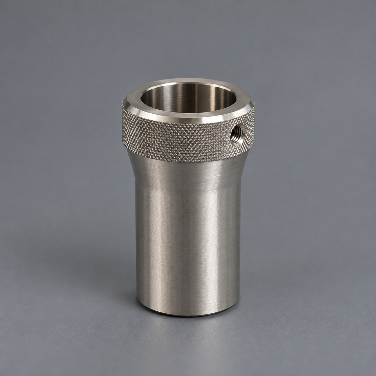
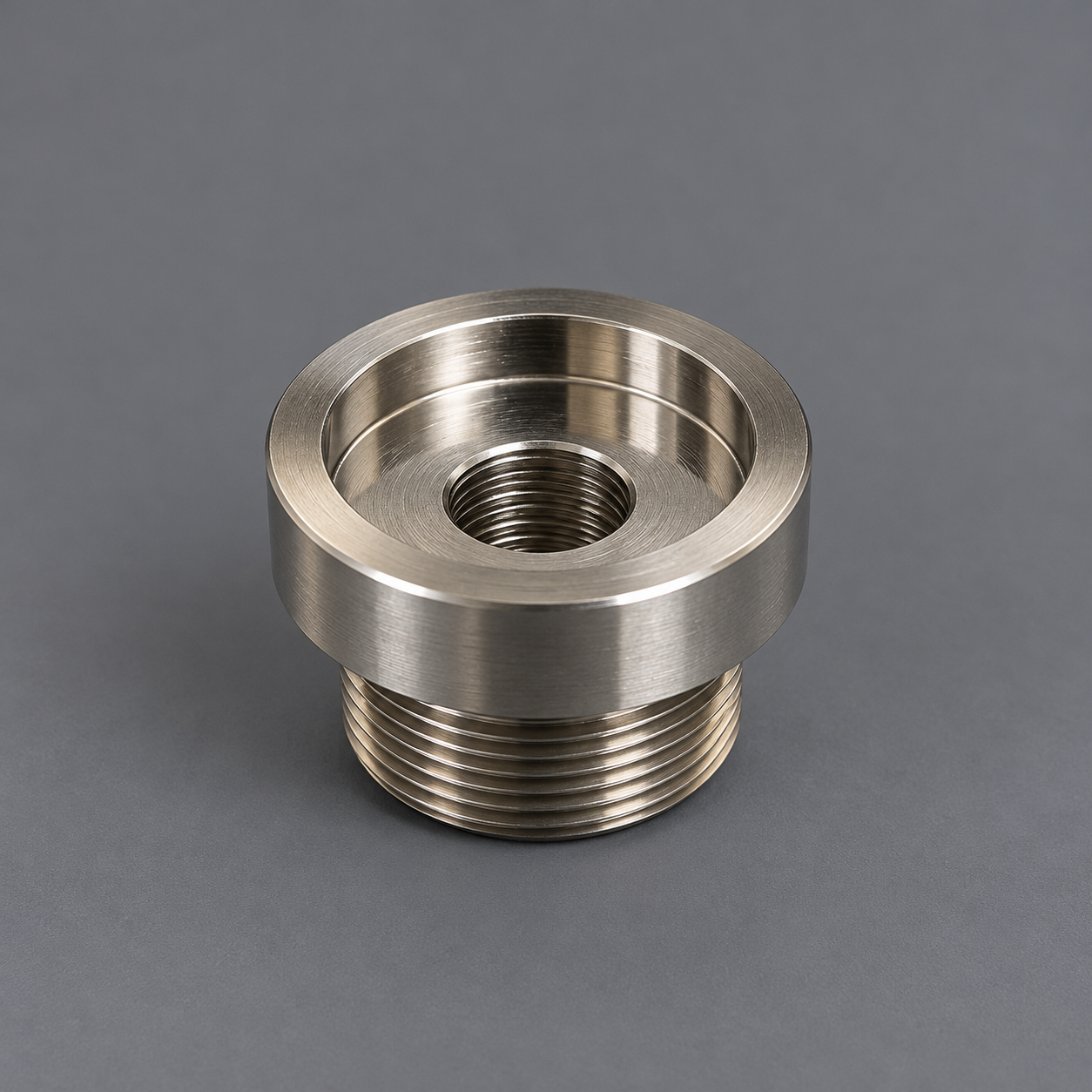
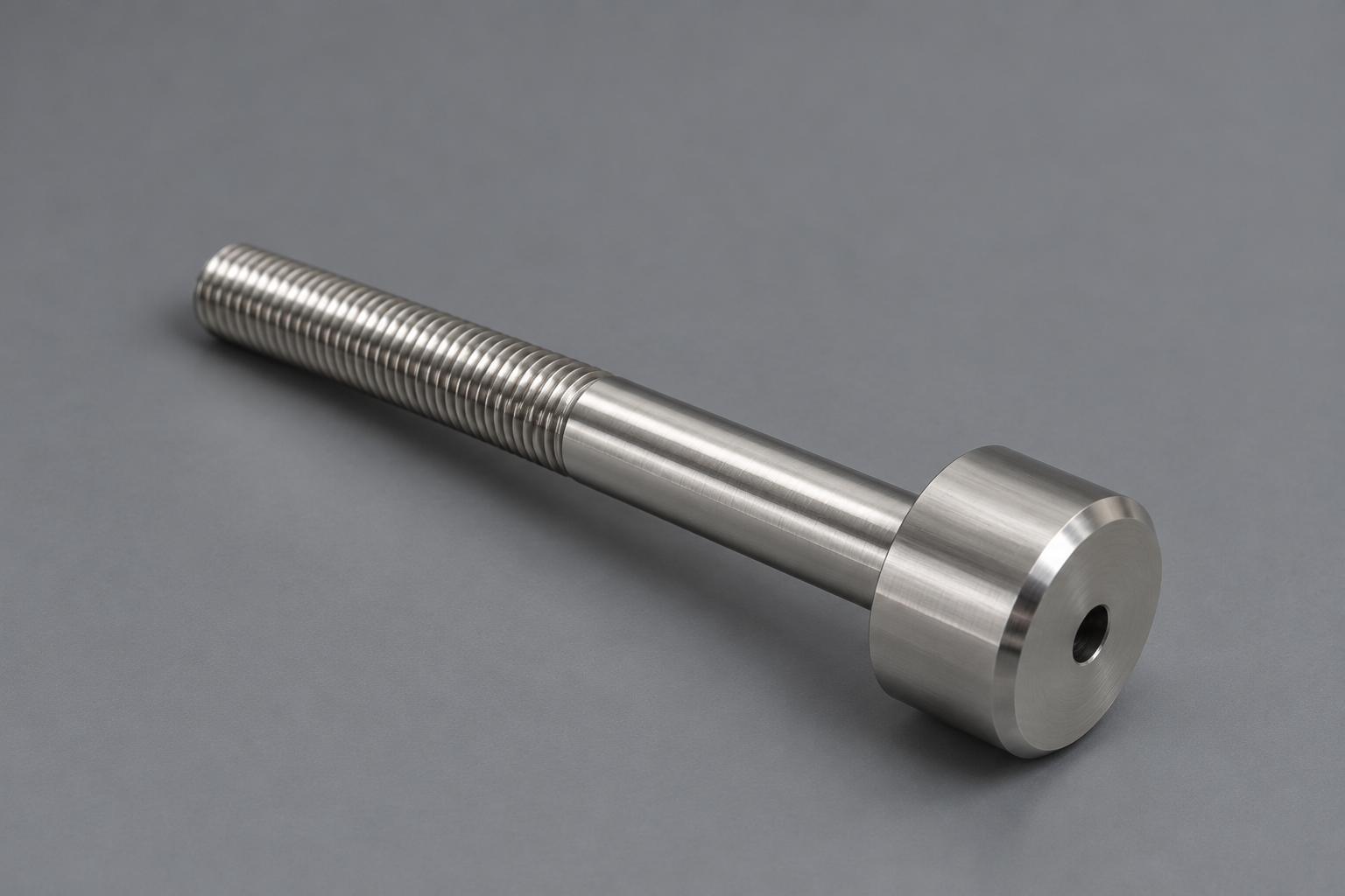
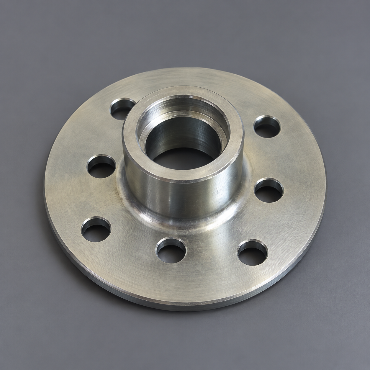
Manufacture of a compact precision threaded adapter with an integral locating flange and stepped internal geometry. The component combines a Ø34 mm flanged head, a Ø32 mm controlled outside diameter, a Ø14.10 +0.05/-0.00 mm center bore and multiple axial steps within a total length of 25 mm.
The drawing does not state the final machine or assembly. Based on the geometry, the part is best described conservatively as a precision threaded adapter / locating component suitable for inspection fixtures, gauges, alignment tools or other mechanical assemblies requiring repeatable positioning and threaded installation.
Drawing Feature | Requirement / Manufacturing Focus |
Overall Length | 25.00 mm |
Flanged Head | Ø34.00 mm, with 38.00 mm across the flats shown in the end view |
Main Body | Ø32.00 +0.00 / -0.05 mm |
Threaded / Cylindrical Region | Ø30.00 mm reference geometry shown in section |
Center Bore | Ø14.10 +0.05 / -0.00 mm |
Axial Features | 15.00 mm and 5.00 mm lengths; 2.50 mm step |
Edge Requirement | 1.5 × 45° chamfer; break all other edges 0.2 mm unless otherwise noted |
General Tolerance | ±0.05 mm unless otherwise noted |
Previous slide
Next slide
The Challenge
1. Tight general dimensional control: unless otherwise noted, the drawing specifies ±0.05 mm. For a compact turned component with several shoulders and recesses, small axial errors can accumulate and affect the final stack-up.
2. Controlled center bore: the Ø14.10 mm bore has a unilateral +0.05/-0.00 mm tolerance. This feature may act as a locating, clearance or mating bore, so undersize conditions are not acceptable.
3. Concentric geometry: the center bore, Ø32 mm body, threaded/cylindrical region and flanged head share the same functional axis. Poor concentricity can cause eccentric assembly, uneven contact or inaccurate positioning in a fixture.
4. Multiple short axial steps: the 5.00 mm, 15.00 mm and 2.50 mm features require careful tool positioning and shoulder control. Tool nose radius and chamfer transitions must not consume the specified functional lengths.
5. Thread and flange interaction: the threaded body must assemble freely while the flange provides a repeatable seating surface. Burrs, damaged thread starts or an uneven flange face can prevent consistent installation.
6. Surface and edge quality: the drawing requires a 1.5 × 45° chamfer at the specified location and 0.2 mm edge breaks elsewhere. The finished component must remain clean and burr-free without rounding functional shoulders.
Previous slide
Next slide
Our Solution
Machine the component primarily in a CNC lathe so the center bore, main outside diameters, shoulders and thread are produced from a common rotational datum, improving concentricity and reducing setup-to-setup error.
Rough and finish the Ø14.10 bore separately, using a boring tool or precision reaming process as appropriate. Verify the final bore with a calibrated bore gauge or GO/NO-GO plug gauge to ensure it remains within +0.05/-0.00 mm.
Finish the Ø32.00 +0.00/-0.05 mm body and the flange seating face in the same controlled setup where practical. Use in-process measurement to prevent cumulative axial error across the 5.00, 15.00 and 2.50 mm stepped features.
Produce the external thread with a stable CNC threading cycle and verify thread fit with the corresponding ring gauge or mating master. Control the thread start and relief so the mating part can seat fully against the flange.
Machine the required 1.5 × 45° chamfer and apply the specified 0.2 mm edge breaks without affecting the locating surfaces. Deburr the center bore and thread carefully to prevent raised edges.
Final inspection records the overall length, flange geometry, Ø32 body, Ø14.10 bore and critical axial steps. For repeat production, a dedicated inspection plan and functional gauges can be used to improve consistency and inspection speed.
Project Results
The controlled turning and inspection process produces a compact adapter with repeatable concentricity, reliable thread engagement and consistent flange seating. Maintaining the Ø14.10 bore and Ø32 mm body within their specified limits supports accurate mating and reduces the risk of assembly play, interference or positional error.
This manufacturing approach is well suited to precision fixture, inspection and alignment components where small dimensional deviations can influence repeatability. The same process can be scaled from prototype quantities to repeat production with documented dimensional inspection and functional gauge checks.
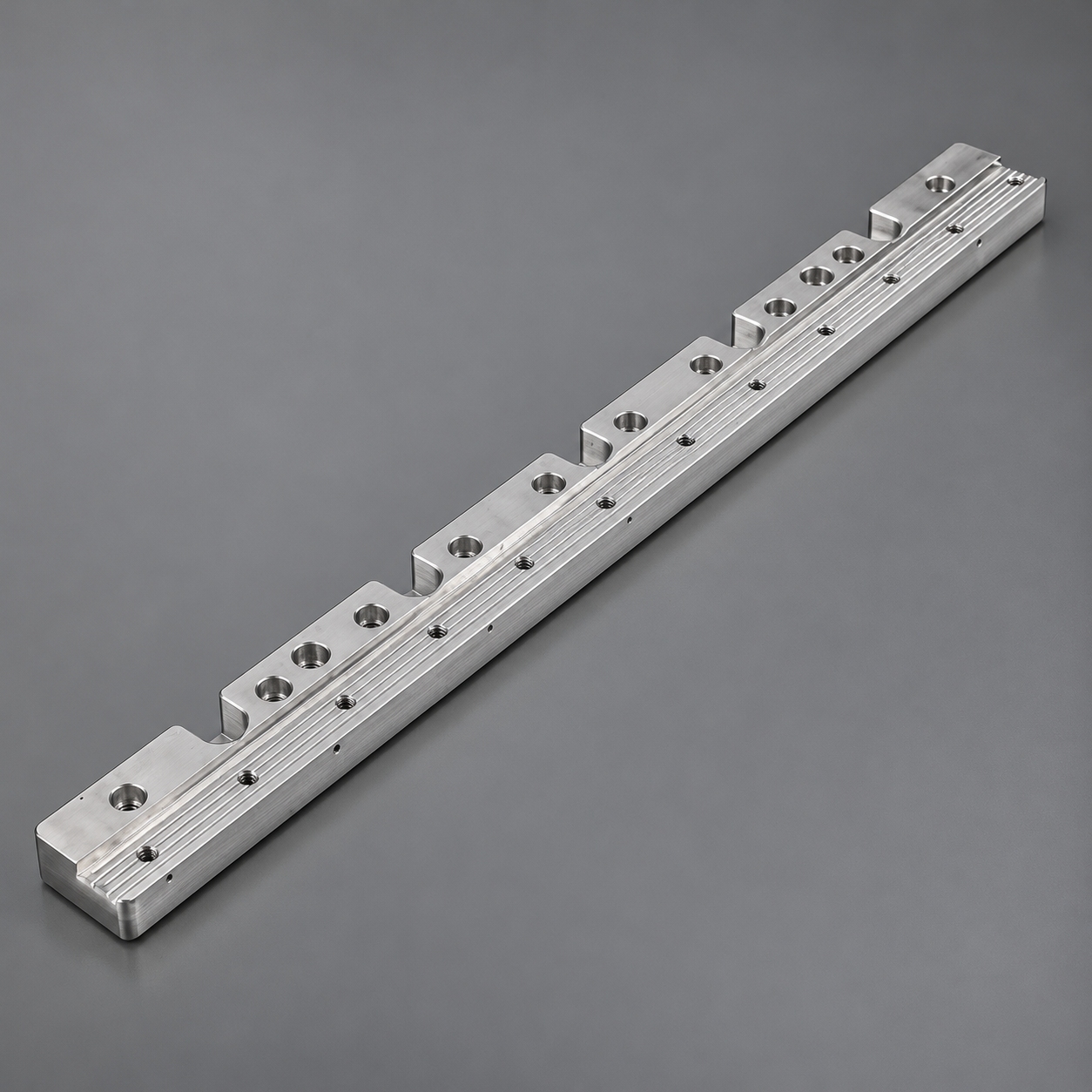
Project Photos

Customer Feedback
“
The tooling quality exceeded our expectations. The parts met all requirements and the lead time was impressive. We highly recommend their rapid tooling service.
— Project Manager, Automotive Lighting Company
Why Choose Us
10+ Years
Industry Experience
1000+
Successful Projects
Advanced Equipment
Precision Manufacturing
Strict Quality Control
ISO 9001 Certified
Global Service
Local Support