

CNC MACHINED 4130 SHOCK MOUNT
From concept to production in 25 days High-quality, cost-efficient rapid tooling solution.
25 Days
Total Lead Time
±0.02 mm
Precision Tolerance
100K+ Shots
Mold Life
0 PPM
Quality Target
Project Overview
This project involved manufacturing a CNC-machined shock mount for an off-road / performance suspension application. The customer’s business focuses on long-travel suspension, chassis and fabrication components, and its product range includes shock-mount clevises, billet shock components and 4130 suspension structures.
The supplied production drawing identifies the component as “SHOCK MOUNT MACHINE 1” in 4130 alloy steel. The geometry combines a cylindrical upper section with a forked clevis, two transverse mounting holes and blended internal radii. Based on the drawing and the customer’s product range, the part is best described as a structural shock-mount / clevis component intended to connect a shock or related suspension member to a fabricated vehicle structure. The exact installation position is not claimed because it is not specified on the part drawing.
MATERIAL | PART | WEIGHT | GENERAL TOL. |
SURFACE | PROCESS | KEY Ø | MOUNT HOLES |
Previous slide
Next slide
The Challenge
The main manufacturing challenge was the relationship between the functional features rather than any single dimension.
The drawing calls out a Ø44.2 ±0.05 mm cylindrical feature, Ø12.7 +0.05/0 mm mounting holes, datum references and geometric controls, while unspecified dimensions follow ISO 2768-fK. The clevis also contains a deep open profile with blended radii and two relatively slender ears.
For this type of suspension component, accumulated setup error can affect the alignment between the cylindrical locating feature, clevis faces and transverse holes. Workholding therefore had to provide enough rigidity for material removal while protecting the finished geometry and avoiding visible clamp damage. The internal pocket and curved transitions also required tool-access planning to avoid chatter, steps or heavy cutter marks.
Previous slide
Next slide
Tight Tolerance
Critical dimensions required ±0.02 mm tolerance.
Short Lead Time
Tooling and samples requested within 4 weeks.
High Cosmetic Requirement
No flow marks, no weld lines, high gloss surface.
Our Solution
We planned the machining sequence around the functional datum structure and divided the part into controlled turning and milling operations.
The cylindrical section was established first as a stable machining reference. The clevis opening, side profiles and blended internal surfaces were then CNC milled with controlled workholding. The transverse holes were finish-machined after the main clevis geometry so their size and relationship to the surrounding features could be maintained.
Particular attention was given to the Ø44.2 mm locating diameter, the Ø12.7 mm mounting holes, symmetry between the two clevis ears, the transition radii and the drawing’s Ra 3.2 surface requirement. Final deburring was carried out without aggressively rounding functional edges or altering critical dimensions.
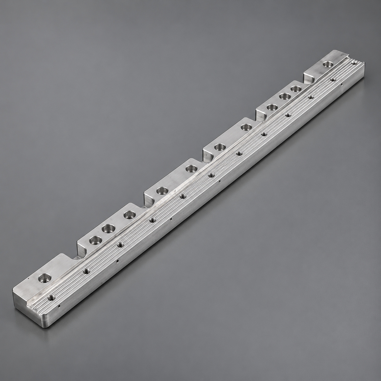
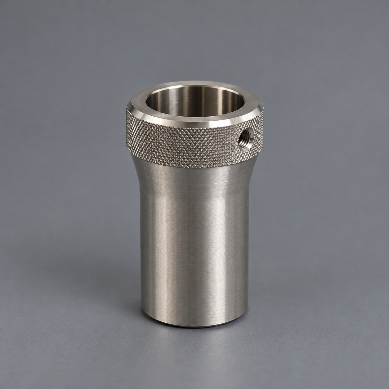
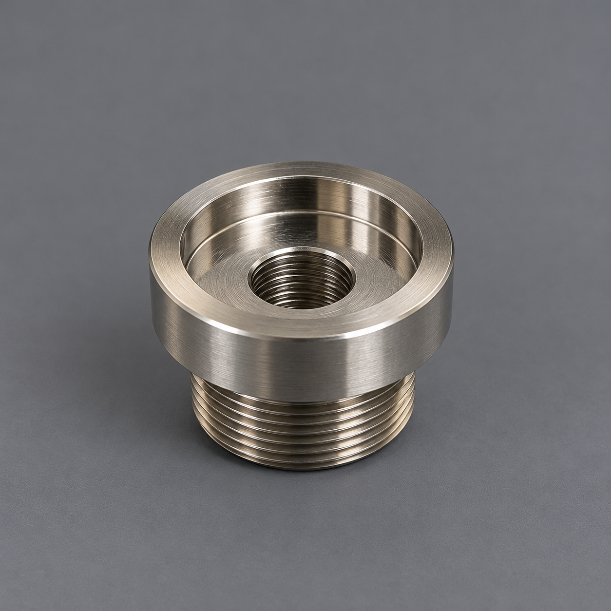
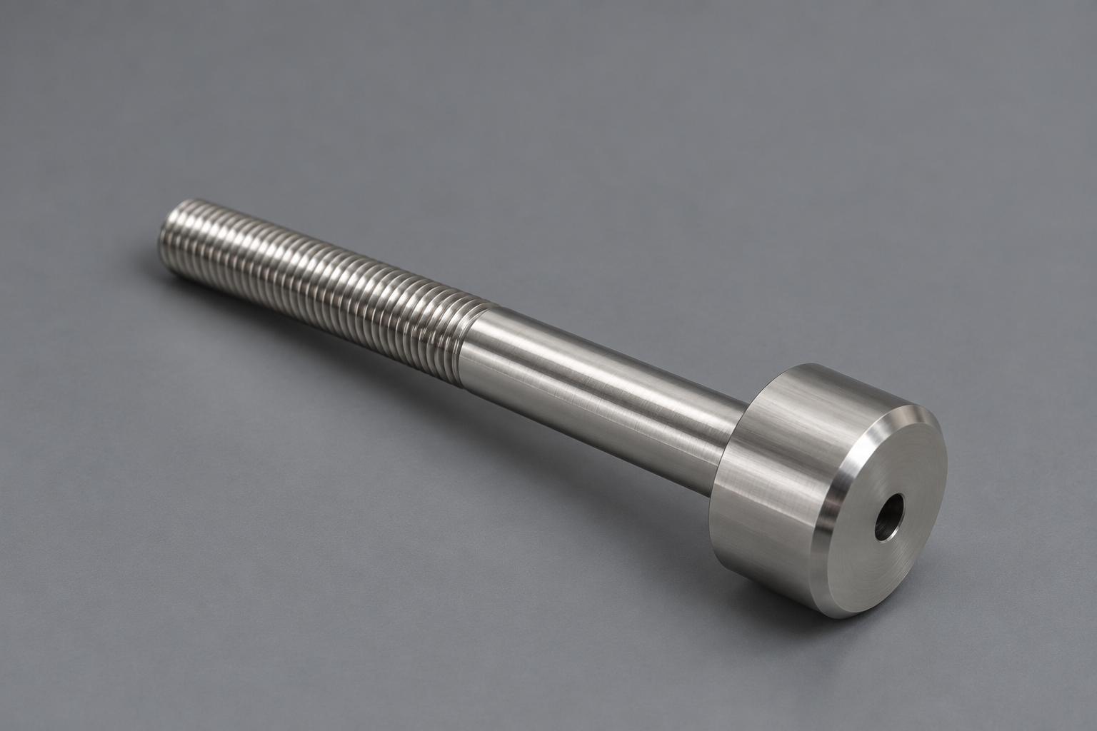
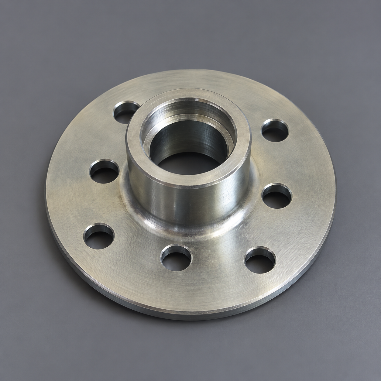
The production photos provide traceable visual evidence of the actual machined component: the fork geometry, deep internal profile, cylindrical section and finished transition surfaces are all visible rather than represented only by a rendering.
DFM Analysis
1–2 Days
Rapid Tool Design
3–5 Days
CNC Machining
7–10 Days
Assembly & Testing
3–5 Days
Sample Approval
25 Days
Project Results
The completed parts showed clean machined surfaces, a consistent clevis profile and well-defined mounting features suitable for subsequent assembly into the customer’s suspension system.
The project demonstrates practical capability in machining 4130 structural vehicle components where turning, multi-face milling, hole alignment, datum control and finish quality must be managed together.
For UTM Industrial, the value of this case is not a generic claim of “high precision.” It is documented manufacturing experience: a real customer drawing, real production parts and visible finished geometry. This makes the project representative of the type of CNC work we support for off-road, motorsport and custom vehicle applications.
Days Total Lead Time
0
Precision Tolerance
±
0
mm
Shots Mold Life
0
k+
Quality Target
0
PPM
On-time Delivery
0
%
Project Photos

Customer Feedback
“
The tooling quality exceeded our expectations. The parts met all requirements and the lead time was impressive. We highly recommend their rapid tooling service.
— Project Manager, Automotive Lighting Company
Why Choose Us
10+ Years
Industry Experience
1000+
Successful Projects
Advanced Equipment
Precision Manufacturing
Strict Quality Control
ISO 9001 Certified
Global Service
Local Support